
About This File
UPDATE: I noticed lots of people are downloading the model files one at a time. It's much easier to download the complete package and avoid the download limits. Here's the zip: ServoIris.zip
UPDATE: There are pictures illustrating the assembly process in my build diary. Note that there are two iris versions in the diary. This is the second one.
This is a complete set of 3d objects to create a micro servo driven iris insert. It is designed to fit into this eye with a little bit of sanding and work with this servo and this LED disk. All parts have the proper clearances based on my printer using .2mm layers. Some of these are pretty close to the wire and you might have to fiddle a bit. I printed everything but the LensPlate using white ABS and painted various surfaces black. The LensPlate is translucent blue ABS with an acetone vapor bath. The leafs and SlotRing were lightly sanded smooth.
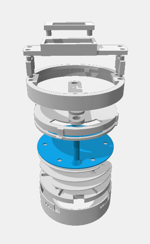
Objects included (bottom up):
- Casing
- SlotRing
- peg (6 required)
- leaf (6 required, note the stl file is flagged as broken and can't be repaired, but it prints ok. Don't use a raft.)
- LensPlate (print using translucent filament)
- [LED disk]
- LockRing (orients with tabs at the top)
- DualSlotLEDPlate (LED disk attaches to this)
- ServoArm (servo horn fits inside)
- [servo horn]
- ServoArmCover
- ServoMountRing
- ServoStandoff (2 required)
- ServoMount
- [servo]
- ServoMountCap
Check out my build diary for pictures illustrating assembly described below. Note that there are two iris versions in the diary. This is the second one.
Assemble the Bottom Iris Section
Assemble the slot ring into the casing. Spray the front and inner lip flat black.
You will need to print 6 each of the leafs and pegs. Then assemble each peg and leaf so that the peg sticks out the opposite side from the post on the leaf. Give them a light sanding to get them smooth. Now paint them flat black and sand smooth again. Leaf assemblies orient with the offset post (the one printed as part of the leaf) down. You have to get all 6 properly nested.
The LensPlate is printed with blue translucent filament and acetone vapor bath smoothed out. Orienting this piece is the tricky part. You will probably have to spin it a few times to figure out which way works. LockRing goes on top of the LensPlate and fits the slots of the casing. You have to clear out the tiny support thingies on the casing btw. Orient the LockRing with the tabs on top.
The LED disk has 4 holes punched in it. Find the pair that fits the DualSlotLEDPlate and press it on with the wires through the hole. Then add the plate to the stack with the LED facing down. The posts on the LensPlate should be at one end of the slots and should move within the slots to open and close the iris. If this is not the case, try disassembling and rotating the LensPlate one step around the leafs until you find the way that works.
At this point you should be able to operate the iris by hand. This is a good time to sand the outside of the casing and inside of the eye front until they fit together properly.
Assemble the Top Servo Section
I used the micro servo with feedback from Adafruit. Eventually I plan to use the feedback wire to know the servo's current position. I believe the non-feedback micro server is slightly different and probably won't fit this mount. You could use a different servo but would have to adapt the ServoMount and ServoMountCap. Trap the servo between the ServoMount and ServoMountCap so that the servo shaft is in the center of the mount. The pieces should fit together snugly.
The servo comes with several horns. Find the one that matches the hollow in the ServoArm. Trap the horn between the ServoArm and ServoArmCap and snap the pieces together. It only fits one way.
Rotate the servo shaft by hand to determine the limits and set it to the center of its range. Attach the arm assembly to the shaft so it is at a right angle to the servo mount and secure it with the screw.
Assemble the servo assembly, two ServoStandoffs, and the ServoMount Ring. If the standoff pegs are too tight, lightly ream out the holes.
Final Assembly
Operate the iris by hand so it is at the halfway point. Attach the servo assembly to the iris. Everything should be properly oriented and the servo assembly should fit snugly on the casing. Make sure all the tabs are lined up. Try operating the servo arm by hand and verify the iris opens and closes. It will not close 100% and will probably not reach the limit on the slots.
Now you have to connect it all up. I used an RJ45 socket and ethernet cable connected to a Raspberry Pi with Adafruit servo/PWM and PifaceRelayPlus HATs. Here's the software. You will have to experiment with the servo to determine what relay and PWM values to use.
Here's the zipped objects: ServoIris.zip